

1. Introduction
2. Methodology
2.1. Characterization of the raw materials
2.2. Synthesis and characterization of CSA cement
3. Results and Discussion
3.1. Synthesis and characterization of CSA cement
4. Conclusions
1. Introduction
In 2020, world production of mollusks, mainly bivalves, reached 17.7 million tonnes (USD 29.8 billion)1). According to the Food and Agriculture Organization of the United Nations (FAO), Asia has become the principal producer of mollusks, followed by Europe and the Americas1). The most representative bivalve mollusk species for trade are scallops, clams, oysters, and mussels. Korea is the second largest mollusk producer (415 thousand tonnes) in 20201). According to Wijsman et al., in 2017, Asia produced 5.1 million oysters2). South Korea produced about 326,000 tons of oysters in 20193,4). In oyster production, the shells are a by-product of the industry and represent 37 to 70% of the oysters5). It implies an enormous amount of residues generated. This generation will increase since the consumption of these mollusks is rising worldwide. Most of this waste is deposited into landfills, abandoned on land, or returned to the sea6). In Korea, approximately 320,000 tons of shells have been discarded into public waters and lands over the past 30 years7). This method of final disposal has caused environmental problems such as odors, water pollution, accumulation, and further defacements of lands6,7,8).
Part of the oyster shells are used as fertilizer and cattle feed. However, finding other essential uses of this waste is necessary. Oyster waste has been investigated as a substitute for fine aggregates or cement in concrete9,10). However, Kuo et al. concluded that only 5% of the fine aggregate could be replaced with pulverized oyster shells11). Instead, the cement industry is finding new uses for other by-products, slag, or wastes that can replace the commonly used materials for producing less polluting cement. Limestone (CaCO3) is the primary calcium-containing mineral used in the cement indystrt due to its abundance. However, some works have replaced the usage of limestone with other calcium-rich wastes. Among these wastes, oysters and other shells have become a significant source of calcium carbonate since otherwise, the final disposal of these shells is a problem. The chemical composition of limestone is similar to oyster shells. Consequently, this could be an effective alternative for producing OPC. For example, Her et al. replaced pulverized oyster and scallop shells in the formulation of cement clinker8).
Climate change has become a global issue of extreme importance in recent decades. Hence, the industry has focused on its mitigation. Further, the cement industry, the world’s largest manufacturing industry, is responsible for around 8% of global CO2 emissions. The emissions produced by limestone calcination and the combustion of fuels required to reach high temperatures in conventional cement rotary kilns (~1,500℃) are the principal causes of pollution12,13). For example, Gartner estimated that 0.28 tones of CO2 is produced per ton of clinker when bituminous coal is used in a modern rotary kiln13). In addition, the world’s cement production every year is around 4 billion tons14). These environmental problems have led to active efforts to seek alternative solutions to reduce its excessive carbon emissions. Thus, the scientific community has focused on developing more environmentally friendly cementitious materials. One of the most practical alternatives is calcium sulfoaluminate cement (CSA). The temperatures required for synthesizing CSA are between 1,100 and 1,250℃. Accordingly, it is considered an eco-cement since its production could reduce carbon emissions by 30 to 40% compared to OPC production, keeping the mechanical strengths required in these cementitious materials15,16). Additionally, the amount of limestone needed for CSA is less than that required for producing OPC15). OPC requires around 75 wt.% of limestone, but CSA only requires 50 wt.%15,17).
The principal mineral phase of CSA cement is ye’elimite (3CaO·3Al2O3·CaSO4). CSA cement has been used for decades as a binder in concrete for bridges, airports, and runways or wherever the setting time is short for quick use. CSA cement concrete experiences rapid precipitation of ettringite (3CaO·Al2O3·3CaSO4·32H2O) forming an interlocking matrix, which produces CSA that has high early strengths (21 MPa at 1.5 h, 34.5 MPa at 3 h, and 55 MPa at 24 h), low shrinkage, and does not expel excess of water in the cement, commonly known as bleeding15). Commonly, CSA cement is produced from limestone, bauxite (Al(OH)3), and gypsum (CaSO4·2H2O). However, different authors have reported that CSA clinker could be synthesized from multiple waste materials and industrial byproducts, i.e., blast furnace slag, aluminum sludge, fly ash, and kiln dust15,18). In the production of CSA, the raw materials require a high percentage of aluminum and sulfur. Hence, alunite (KAl3(SO4)2(OH)6), a hydroxylated aluminum potassium sulfate mineral, is the ideal mineral for producing this kind of cement.
Alunite has been used as a potassium and aluminum resource since the Roman period19). Alunite is found near volcanoes or volcanic rocks. Some of the most representative deposits are located in Tolfa (Italy), Badacsony (Hungary), New Wales (Australia), Gasado (South Korea), or Utah and Arizona (USA). Nonetheless, alunite ore contains quartz and other minerals (dickite, kaolinite, pyrophyllite) which principally contain SiO2. According to Eq. (1), alunite ore reacts with calcium carbonate (CaCO3) to form ye’elimite(Ca4(AlO2)·6SO4). However, the quartz contained in this ore reacts with calcium carbonate, forming wollastonite (α-CaO·SiO2) and larnite(β-2CaO·SiO2). Besides, the aluminum contained in alunite can react with silica and limestone, forming gehlenite(2CaO·Al2O3·SiO2). Gehlenite reduces the reactivity of CSA cement as it has low reactivity and does not actively participates in hydration20).
Even though some studies have specified the possibility of using waste oyster shells in cement production, a proper replacement of limestone with this waste has not been reported. Thus, this work aims to synthesize calcium aluminum oxide sulfate (CSA) using alunite and oyster shells, as a practical way to reuse this waste. This work analyzes the thermal decomposition characteristics of the raw materials and then determines the best temperature and molar ratio to synthesize the clinker. The characteristics of the raw materials and synthesized clinkers were analyzed by scanning electron microscopy (SEM), X-ray diffraction (XRD), X-ray fluorescence spectrometer (XRF), thermo-gravimetric Analyzer (TGA), and compressive strength for the mortar.
2. Methodology
2.1. Characterization of the raw materials
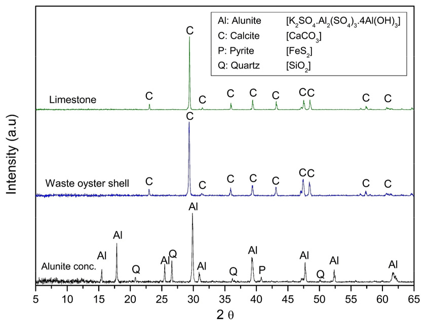
This work used an alunite concentrate (d90 < 75 μm) collected from Haenam, a county in the South Jeolla Province, South Korea. The crushed limestone (d90 < 75 μm) was obtained from Danyang, North Chungcheong Province. The waste oyster shells (Crassostrea gigas) were collected from Tongyeong, a coastal city in the South Gyeongsang Province, South Korea. The shells were soaked in water for 30 min and rinsed. This procedure was repeated 3 times to remove any organic residue and odor. All the samples were dried in an oven at 105℃ for 48 h. The waste oyster shells were crushed using a jaw crusher and then pulverized in a rod mill to produce a fine powder (d90 < 75 μm). An X-ray fluorescence spectrometer (XRF; XRF-1800, Shimadzu, Japan) was used to determine the chemical composition of the raw materials used in this study. Besides, the mineral composition was analyzed using an X-ray diffractometer (XRD; Bruker D8 Advance A25, Bruker-AXS, Germany). The diffractogram was obtained for 2θ values from 5 to 65° with a divergence slit of 0.3°, a Soller slit of 2.5°, and a sample rotation speed of 12 RPM. The results are displayed in Table 1 and Fig. 1, respectively. The weight loss and thermal transition of the samples were determined using a Thermo-Gravimetric Analyzer (TGA; DTG-60, Shimadzu, Japan) under air and CO2 flow from 25℃ to 1,000℃ at a heating rate of 10℃/min, and a flow rate of 80 ml/min.
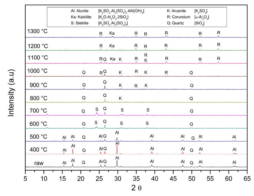
Fig. 1 shows the X-ray powder diffraction patterns of all the raw materials used in this work. Alunite concentrate contains alunite (K2SO4·Al2(SO4)3·4Al(OH)3; JCPDS 01-071-1776), quartz (SiO2; JCPDS 33-1161) as impurity, and some traces of pyrite (FeS2; JCPDS 42-1340). As expected, limestone and the waste oyster shell are formed of calcite (CaCO3; JCPDS 05-0586). Whereas it was expected to have traces of halite (NaCl) in the shells due to the provenance, the XRD did not mark any trace of this mineral. In contrast, Table 1 shows the Na2O and chloride ions (Cl-) concentrations in the waste oyster shell are 0.75 wt.% and 0.50 wt.%, respectively.
Table 1.
Chemical composition of the raw materials used in this study
2.1.1. Characterization of the oyster shells and limestone
The crustal structure of oyster shells have several distinct layers22). The peripheral layer is a protein called conchiolin. Conchiolins are complex proteins that are secreted by a mollusk’s outer epithelium. The microstructure of the internal layer includes 3 layers: The regular simple prismatic (RSP) layer, the Regular foliated (RF), and the chalk microstructure (CM) layer. The RSP layer has prismatic units that are separated by organic walls. The RF layers are foliated laths, separated by a thin layer of organic matrix. The CM layer is porous and includes relatively large blades and small leaflets22). Fig. 2 shows the structure of the shell and its different layers. The CM layer is the most prominent in the shell. However, the RSP layer is fragile and difficult to observe. Ha et al. concluded similarly with this work by observing oyster shells from Tongyeong22). Fig. 2(c) shows the irregular shape of the RSP layer. In contrast, Fig. 2(d) shows the rounded regular shape of limestone. The texture of limestone has been reported to affect the calcination products22).
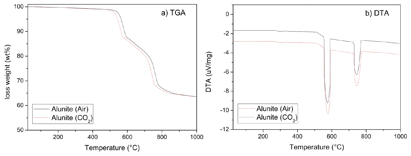
Thermal analysis results of oyster shells and limestone show similar decomposition behavior trends, as Fig. 3 emphasizes. When air was used, CaCO3 started to decompose, denoted in its loss weight, from 700℃ and finished at 840℃. This temperature matches its theoretical decomposition temperature (825℃). Conversely, oyster shells have a gradual weight loss that started at lower temperatures compared to limestone, as Fig. 3 emphasizes. It is determinable to the decomposition of the conchiolins presented in the RSP, and RF layers22). Balmain, Hannoyer, and Lopez reported that the organic matrix in shells is strongly linked to calcite, and has high thermal stability23). This proteins are destroyed at around 550 to 600℃. Oyster shell calcination is completed at 800℃. Moreover, Fig. 3(b) shows the differential thermal analysis (DTA) of oyster shells and limestone. It denoted the endothermic reaction of CaCO3, expressed in Eq. (2). This reaction occurs at higher temperatures in limestone than in oysters.
Several factors, including the organic configuration and impurities such as SiO2, Al2O3, and Fe2O3, can affect the calcination temperature22). However, the principal cause is the organic matrix in shells that may affect the decomposition temperature, compared with limestone, and the texture, as Fig. 2(c) and Fig. 2(d) denoted. Fig. 2(c) shows that oyster shells comprise small prisms, foliated planks, and irregularly shaped forms. These forms reduce the thermal stability. Consequently, it is easier to decompose and enhance the outflow of the produced CO2. As a result, compared with limestone, calcination occurs at lower temperatures.
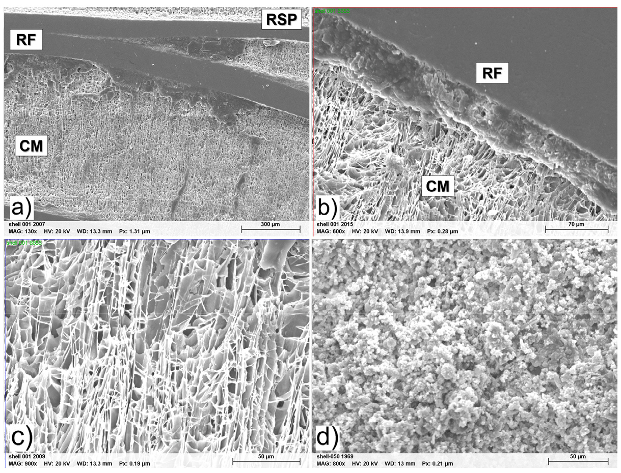
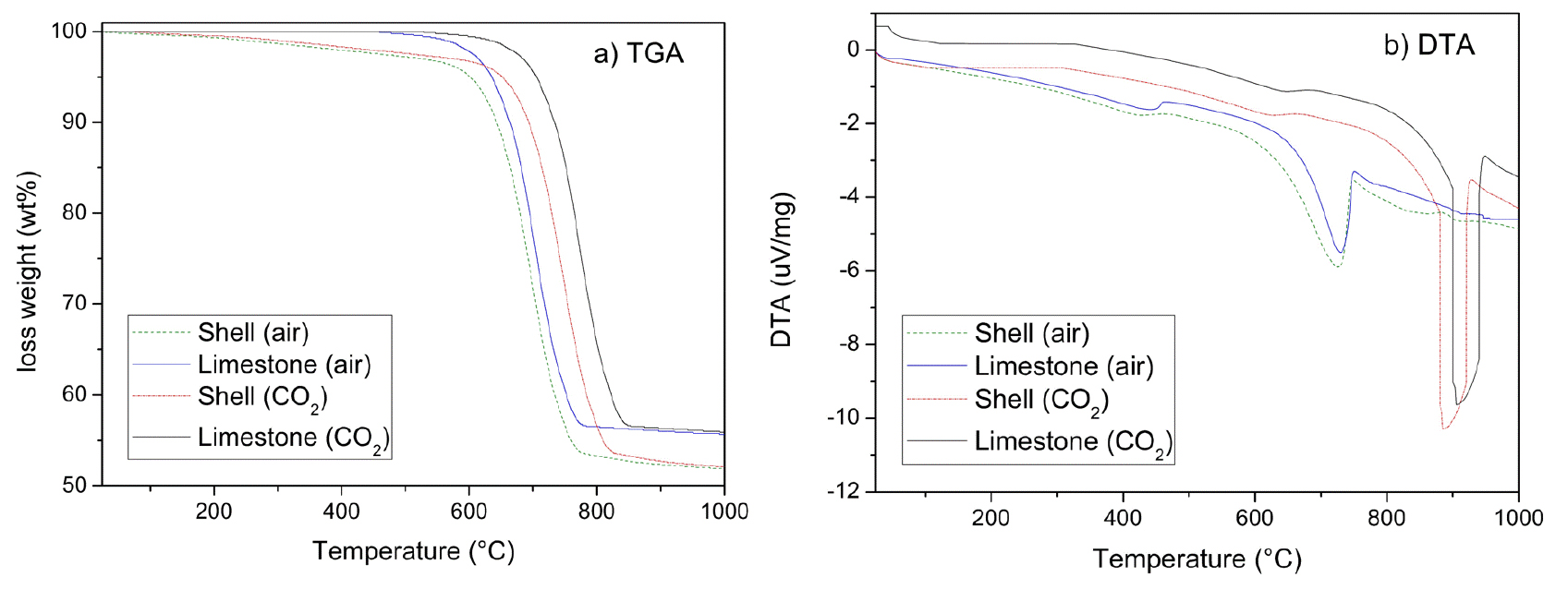
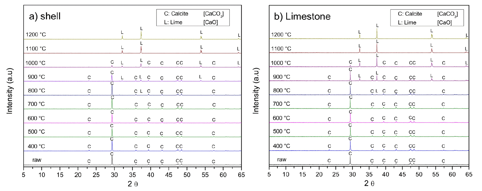
Fig. 4 presents the XRD analysis of oyster shells and limestone subjected to calcination at different temperatures for one hour. As the temperature increases, the intensities of the calcite peaks decrease, while lime (CaO) peaks become more pronounced. At 800℃, only a small quantity of calcite decomposes to form lime. From 900℃, the decomposition of calcite accelerates, leading to a progressive increase in lime formation. At 1,000℃, the remaining calcite content in limestone is lower than that in oyster shells. This difference arises from variations in structural properties and decomposition kinetics. As shown in Fig. 2(c), the chalk microstructure of oyster shells results in a highly porous and less compact framework compared to the interlocking mineral grains of limestone in Fig. 2(d). This porous anatomy enhances CO2 diffusion, facilitating more efficient calcination. In contrast, the denser mineral structure of limestone hinders gas escape, thereby slowing down decomposition. Beyond 1,100℃, calcite is fully decomposed into lime, as indicated by the complete disappearance of calcite peaks in the XRD patterns
2.1.2. Characterization of the alunite
Fig. 5 shows the Thermal analysis results of alunite. Alunite shows two principal thermal decomposition processes: dehydroxylation and desulfurization, regardless of using air or CO2. Alunite (K2SO4·Al2(SO4)3·4Al(OH)3) is transformed into steklite (K2SO4·Al2(SO4)3) and corundum (α-Al2O3), as Eq. (3) denoted. This dehydroxylation occurs from 500 to 580℃. The weight loss is 11.76 wt.%, as Fig. 1(a) remarks, which matches the theoretical value (13.04 wt.%), according to Eq. (3). The difference is because of the impurities, such as quartz.
After dehydroxylation, SO3(g) is slowly produced by the thermal decomposition of steklite from 580 to 700℃, and the reaction is faster from 700 to 780℃. Eq. (4) shows this desulfurization. Fig. 5(a) indicates a weight loss of 19.86 wt.% (31.62 wt.% total thermal decomposition).
Fig. 6 shows the calcination of the alunite concentrate at different temperatures for one hour. When the temperature increases, the intensities of the alunite XRD peaks decrease. At 600℃, the alunite peaks disappear, and steklite (K2SO4·Al2(SO4)3; JCPDS 23-0767) peaks appear. These results match the TGA and DTA of Fig. 5, and Eq. (3). However, any corundum is appreciable. Corundum peaks are not appreciable because alunite is often poorly crystalline24). Steklite is gradually decreasing when the temperature is increased. At 800℃, steklite is inappreciable, and small peaks of arcanite (K2SO4; JCPDS 01-070-1488) are visible. At 1,000℃, corundum (α-Al2O3; JCPDS 46-1212) peaks began to show. Furthermore, the peaks of quartz are evident and stable until 1,100℃, when they fade. The quartz reacts with the potassium sulfate and corundum to form kalsilite (K2O·Al2O3·2SiO2; JCPDS 11-0579).
2.2. Synthesis and characterization of CSA cement
An elevator electric furnace with eight electrodes made of tungsten carbide (50/60 Hz, 2400 W, 220 V, Hanyang Lab. Scientific Services, Daejeon, South Korea) was used to synthesize CSA from waste oyster shells. Alunite concentrates (d90 < 75 μm) were mixed with the washed shell (d90 < 75 μm) at different ratios and sintered at 1,200℃ for 1 h, with a heat rate of 10℃/min. Other works determined that this temperature is the most suitable for synthesizing CSA from limestone and alunite20,28). According to Eq. (1), the alunite/calcite molar ratio to form one mole of CSA is 1/6 (weight ratio 1/0.73). However, the alunite and calcite were mixed at different ratios. Any mineral changes of the synthesized CSA were analyzed using XRD. After that, the alunite/shell mixture was sintered at various temperatures to define the dynamics of the formation of CSA and the reactions of calcination and sintering. The heat rate was 10℃/min. After the synthesis of CSA, every sample was analyzed by XRD.
Compressive strength testing of mortar incorporating the synthesized CSA was conducted. Ordinary Portland Cement (OPC) was mixed with CSA at a 10:1 weight ratio, with CSA synthesized varying alunite-to-shell molar ratios and temperatures. The mortar was prepared using standard sand, in accordance with ASTM C778 (grain size distribution of 0.08~2.00 mm, maximum moisture content of 0.2%, and SiO2 content over 98%), at a 1:3 weight ratio. The mortar was mixed with water at a constant water-to-cement weight ratio (w/c) of 0.48 using a mortar mixer (HJ-1150, Heungjin, Gimpo, South Korea) for 3 min. The paste was cast into 50 mm metal cube molds and cured in a moist chamber (HJ-1451, Heungjin, Gimpo, South Korea) at 20 ± 5°C and 95% relative humidity. After 24 hours, the samples were demolded and stored under the same curing conditions. Compressive strength tests were conducted at 1, 3, 7, and 28 days following ASTM C109/C21). The compressive strength of the cubes was measured using a compressive strength tester (HCT-DP300, Heungjin, Gimpo, South Korea).
3. Results and Discussion
3.1. Synthesis and characterization of CSA cement
3.1.1. Synthesis of CSA cement
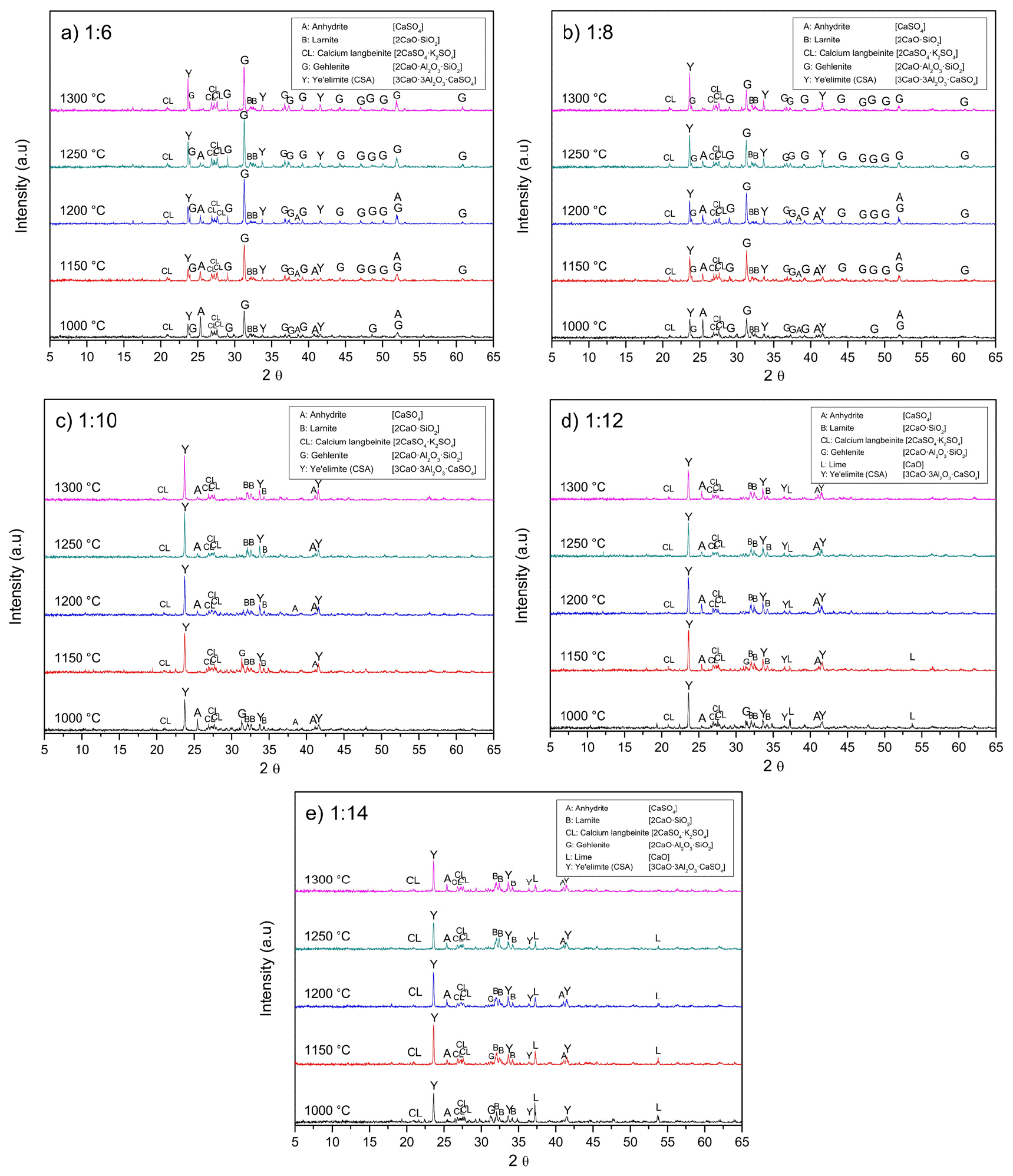
The temperatures required for producing CSA are between 1,100 and 1,250℃. Aranda and De la Torre reported ye’elimite begins to be formed over 1,000℃15). At 1,300℃, the clinker starts to deteriorate due to the melting or decomposition of the phases. Besides, Kim et al. determined that the temperature for producing ye’elimite from chemical reagents should be higher than 1,200℃20). Consequently, this temperature was chosen, as a starting point. Fig. 7 shows the XRD patterns of the sintering of alunite with the shells at 1,200℃ at different molar ratios. It remarks the presence of gehlenite (2CaO·Al2O3·SiO2) at low alunite/shell molar ratios. Gehlenite has a low hydration reactivity, making it unfavorable for cement production25).
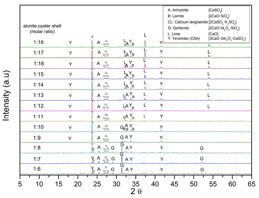
Eq. (5) is a modification of Eq. (1), considering the formation of gehlenite due to the quartz contained in the alunite, used as raw material. Eq. (5) also expresses the presence of anhydrite, calcium langbeinite, and gehlenite as a byproduct, compared with only the occurrence of calcium langbeinite in Eq. (1). According to Eq. (5), the alunite/calcite molar ratio to form one mol of CSA is 2/15 (weight ratio 1/0.91). Gehlenite reacts with CaCO3 and CaSO4 to form ye’elimite and larnite, as Eq. (6) indicates. Eq. (7) was obtained by adding Eq. (5) and Eq. (6). It remarks on the synthesis of CSA without producing gehlenite and the necessity of adding more CaCO3 to reduce its formation. The alunite/CaCO3 molar ratio for Eq. (7) is 1/9 (weight ratio 1/1.10). Eq. (1), Eq. (5), and Eq. (7) mark the reaction of SO3(g) produced during the desulfurization phase in the thermal decomposition of alunite, with CaO, produced during the thermal decomposition of CaCO3, expressed in Eq. (2), to form anhydrite (CaSO4).
Fig. 7 highlights that when the molar ratio of alunite/shells is 1/6, the main products include anhydrite (CaSO4; JCPDS 37-1496), calcium langbeinite (K2SO4·2CaSO4; JCPDS 20-0867), gehlenite (2CaO·Al2O3·SiO2; JCPDS 35-0755), larnite (β-2CaO·SiO2; JCPDS 33-0302), and ye’elimite (3CaO·3Al2O3·CaSO4; JCPDS 01-083-9042). Increasing the molar ratio higher than 1/10 makes gehlenite disappear, increasing the formation of ye’elimite. At a molar ratio of 1/12, an excess of lime (CaO; JCPDS 43-1001) can be observed. The results of Fig. 7 coincide with the result of Kim et al., in which they established that the ratio of CaO/alunite must be higher than 6 (alunite/CaCO3 weight ratio of 0.72) and Ca/SiO2 must be higher than two20). Consequently, an alunite/shell molar ratio of 1/10 was chosen for the following experiments.
Synthesis temperatures are an essential part of the formation of clinker. At low temperatures, the necessary phases could not be produced, affecting the hydration properties of the clinker. Contrariwise, at high temperatures, the components could decompose. For example, CaSO4 decomposes in CaO and SO3(g), affecting the cement properties26). Subsequently, the temperature of firing the clinker needs to be investigated.
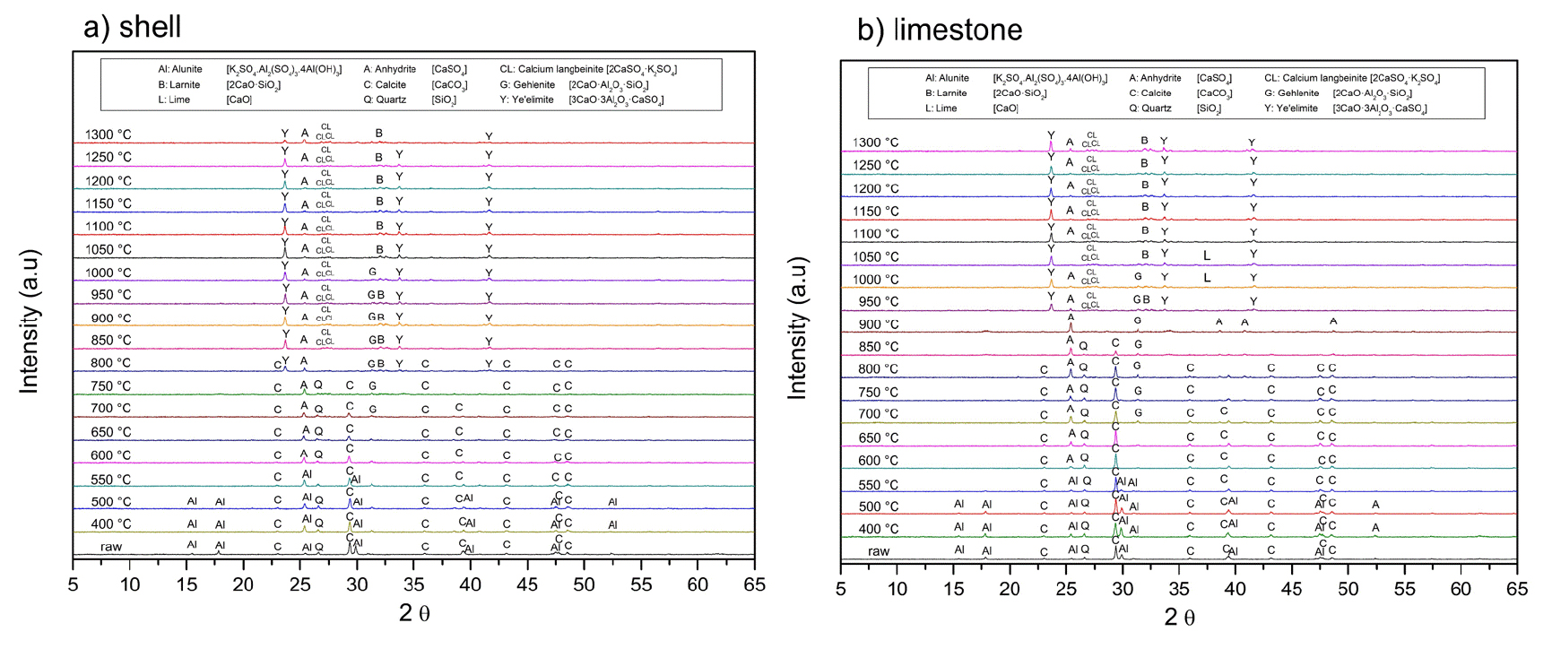
Fig. 8 shows the XRD of the clinkers produced using alunite and waste oyster shells at different temperatures using an alunite/shell molar ratio of 1/10. The alunite peaks decrease below 600℃ while the CaCO3 peaks diminish at 900℃. This phenomenon was better explained in the previous sections. Anhydrite begins to be synthesized from 550℃ in both cases. Anhydrite observed at 650℃ was formed by the reaction of SO3(g) with CaCO3 (direct desulfurization) and at temperatures higher than 650℃, anhydrite was formed by the reaction of SO3(g) with CaO (indirect desulfurization)27). The reaction of calcium langbeinite occurred at 700℃. Gehlenite appears from 700℃, as Eq. (5) denotes, and disappears at 1,050℃, as a product of the reaction expressed in Eq. (7). Ye’elimite begins to be formed at 950℃ when limestone is utilized. However, when shells are employed, the ye’elimite peaks become visible at 800℃. This considerable reduction in the CSA formation is due to a lower thermal decomposition temperature oyster shells have compared with limestone and corroborated with the data shown in the previous section. At 1,000℃, anhydrite reacts with gehlenite to form ye’elimite. This transformation is evident as the peaks of anhydrite and gehlenite decrease, while those of ye’elimite intensify. CSA remains stable up to 1,300℃. Therefore, the optimal temperature range for ye’elimite (CSA cement) formation is between 1,000 and 1,250℃28). Accordingly, the sintering temperature was set at 1,200℃. The final product consists of ye’elimite, anhydrite, calcium langbeinite, and some unreacted lime.
3.1.2. Characterization of the synthesized CSA cement
Fig. 9 shows the XRD of the CSA synthesized from oyster shells and alunite at 1,200℃ at an alunite/shell molar ratio of 1/10. Belite is produced because of the reaction of calcite with SiO2 contained in the alunite. Eq. (7) remarks on the synthesis of larnite as a byproduct of the synthesis of CSA. The excess of quartz reacts independently with calcite to form larnite. Otherwise, adding an excess of CaCO3 to the mix will produce CaO and CO2, as Fig. 7 denoted. Kim et al. found that when the amount of SiO2 is increased from 1 to 5 mol, the quantity of ye’elimite is reduced, increasing the amount of wollastonite (α-CaO·SiO2) and gehlenite20). Additionally, when the amount of CaO is increased, wollastonite decreases, producing larnite. Finally, they conclude that when a CaO/SiO2 ratio exceeds 2, ye’elimite(CSA), calcium langbeinite(K2SO4·2CaSO4), and larnite are stably generated.

Larnite is one of the principal components of OPC cement25). This mineral gives cement the late strength due to its low reactivity29). However, when CSA contains larnite, it blocks CSA cement from developing high strengths at short periods. Hence, it should be avoided. Further, Fig. 9 shows the XRD of CSA synthesized from alunite and limestone at 1,200℃ at an alunite/CaCO3 molar ratio of 1/10. There is no significant difference between the CSA synthesized using oyster shells and limestone. Finally, if these two products are compared with a commercial CSA, shown in Fig. 9, the commercial CSA does not have anhydrite and calcium langbeinite. In addition, the larnite content is lower (3.5 wt.%, compared with 15.9 wt.% and 13.8 wt.% for the CSA synthesized from oyster and limestone, respectively). These results are supported by comparing commercial CSA chemical and mineral composition, shown in Table 2 and Table 3, respectively. Not with standing, anhydrite is a mineral necessary for the hydration of CSA. It could be added to the paste to control the hydration kinetics of CSA30).
The chemical and mineral composition of the synthesized CSA from waste oyster shells is shown in Table 2 and Table 3, respectively. Notably, the chloride content decreased significantly compared to intial expectations. As shown in Table 1, the washed oyster shells used as raw material for CSA sythesis contained 0.5% chloride; however, the resulting clinker retained only 0.007%. Regulatory standards, such as ASTM C150, limit chloride content in concrete to a maximum of 0.3 kg/m2 to prevent salt-induced structural damage31). Typically, producing 1 m2 of concrete requires approximately 320~340 kg/m2 of cement, with around 10% of CSA mixed with OPC. If the chloride content from oyster shells remained in the clinker, it would reach approximately 0.86~0.89 kg/m2, exceeding the regulatory limit by about 0.6 kg/m2 making it unsuitable as concrete additive31). Oyster shells contain minor amounts of sodium chloride (NaCl), and calcium chloride (CaCl2) due to seawater exposure. The melting points of calcium chloride (772℃) and sodium chloride (800.1℃) are significantly lower than the clinkerization temperature required for CSA synthesis. Although a substantial portion of these chlorides volatilizes or is removed during high-temperature sintering, residual chloride content must be carefully controlled to ensure compliance with regulatory limits. Additionary, chlorine volatilization during clinker production poses environmental concerns, as released chlorine compounds can accumulate in the kiln or chimney, potentially obstructing the raw material inlet. To mitigate these issues, implementing a scrubber or bypass system is essential to prevent pollution. Chlorine bypass facilities are commonly employed by environmental treatment companies processing high-chlorine waste and by cement manufacturers using chlorine rich materials32). These systems effectively capture chlorine, maintaining clinker quality and ensuring smooth kiln operation.
Table 2.
Chemical composition of the synthesized CSA cement from waste oyster shells and limestone
Table 3.
Mineral composition of the sintered CSA cement from waste oyster shells and limestone
Fig. 10 shows the CSA synthesized at different temperatures and alunite/oyster molar ratios. Fig. 10(a) and Fig. 10(b) show that at low alunite/shell molar ratios, the calcium content is low to produce CSA. Accordingly, gehlenite (2CaO·Al2O3·SiO2) is produced. However, at higher temperatures, some gehlenite is decomposed and reacts to form CSA, as Fig. 10(a) highlights with the reduction of the principal peak of gehlenite at 31.423°; and the increase of the CSA, and larnite (β-2CaO·SiO2). Also, Fig. 10(c) emphasizes that the optimal alunite/shell molar ratio is 1/10 since the gehlenite content is almost null from 1,200℃. When alunite/oyster molar ratios are higher, the calcite that did not react remains as lime (CaO), as shown in Fig. 10(d) and Fig. 10(e).
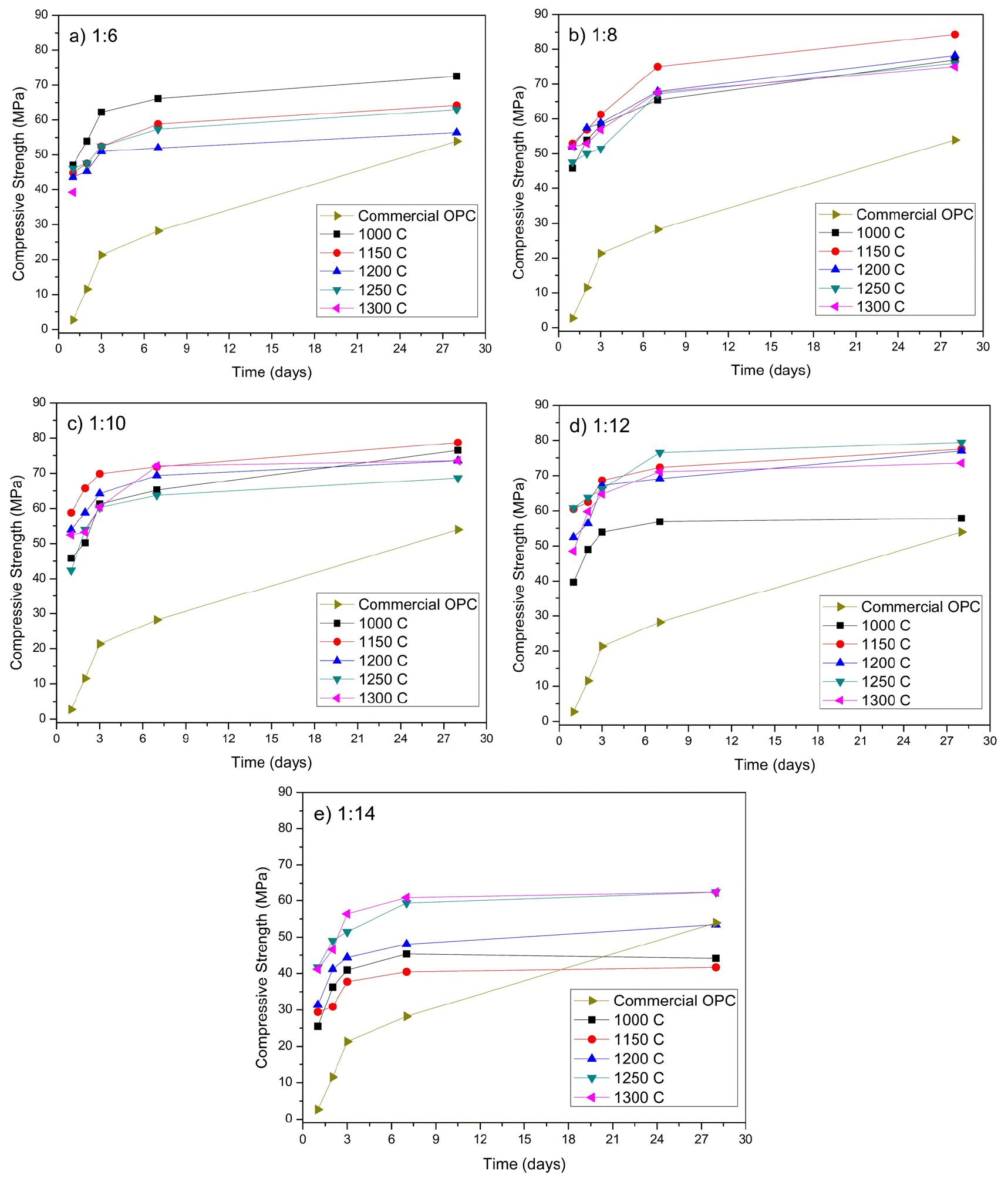
The compressive strength of the OPC mortar mixing at a 10:1 ratio with CSA and cured for 1, 3, 7, and 28 days of analysis is shown in Fig. 11. The OPC mixed with 10% of the synthesized CSA paste showed higher early and late strength. The clinker prepared at an alunite/shell molar ratio of 1/6 and 1,300℃ could be analyzed only at 1 day because the paste was unstable, and after that time, it had expansive cracks. The reduction of ye’elimite and formation of gehlenite, shown in Fig. 10(a), explains this phenomenon. Gehlenite has a low hydration reactivity, affecting the hydraulic properties25).
However, when the content of shells was increased at higher molar ratios than 1/8, the compressive strength was stable. The calcination temperature at which the clinker expresses stable physical properties is preferably 1,000 to 1,250℃. Fig. 11(b) emphasizes that 1,150℃ is the temperature with the highest compressive strength. Fig. 11(c) shows that an alunite/oyster ratio of 1/10 is optimal to obtain the highest compressive strength. The reduction of gehlenite and no excess of lime produce the best conditions for the CSA.
Free lime affects the cement strength by inducing unsoundness. Soundness is the stability of the clinker to any volume change when it is setting and hardening. Free lime may result in undesired expansion and volume instability, making the cement expand and disintegrate. In other words, the paste will crack25). A negative influence of free lime on strength began to appear at about 2 days, reaching greatest significance between 28 and 90 days25,32). The excess of lime reduces the late strength, as Fig. 11(d) and Fig. 11(e) mark when comparing them with Fig. 11(b) and Fig. 11(c).
Fig. 11(c) shows there is not a considerable difference in the compressive strength of the synthesized CSA at different temperatures, Fig. 11(c) shows a lower content of larnite. The difference between the compressive strength at 7 and 28 days is 5 MPa. The compressive strength of CSA cement in 1 day, 3 days, 7 days, and 28 days at 1,150℃ and an alunite/oyster molar ratio of 1/10 are 53.94 MPa, 64.23 MPa, 69.38 MPa, and 73.55 MPa, respectively.
4. Conclusions
Oyster shells experience calcination at lower temperatures than limestone due to differences in chemical composition and microstructure. The irregular and porous shape of shells facilitates CO2 release, enhancing decomposition efficiency, in contrast with the rounded regular shape of limestone. Similarly, alunite exhibits two major thermal decomposition stages: dihydroxylation (500~580℃), and desulfurization (580~780℃), regardless of the surrounding gas atmosphere.
Calcium Sulfoaluminate (CSA) cement was successfully synthesized using alunite and oyster shells, offering a sustaninable approach to shell waste management. The optimal synthesis temperature for CSA ranges between 1,100 and 1,250℃. During calcination, SO3 from alunite reacts with CaCO3 to form anhydrite (CaSO4) at 650℃, while at higher temperatures, SO3 reacts with CaO, product of the calcination of CaCO3. However, quartz impurities in aluinte promote the formation of gehlenite (2CaO·Al2O3·SiO2) and larnite(2CaO·SiO2). The presence of gehlneite decreases as the alunite/shell molar ratio increases.
When oyster shells are used instead of limestone, ye’elimite formation occurs at a consierably lower temperature (800℃, compared with 950℃ using limestone), which is beneficial for energy efficiency. Ye’elimite, the principal constituent of CSA cement remains stable up to 1,300℃. When the molar ratio of alunite/waste shells is 1/6, the main products include anhydrite, calcium langbeinite, gehlenite, and ye’elimite (CSA). Increasing the molar ratio higher than 1/10 makes gehlenite disappear, increasing the formation of ye’elimite. With the molar ratio of 1/12, an excess of lime can be observed. The excess of quartz reacts independently with CaCO3 to form larnite and expels CO2. Also, The chloride content in CSA cement was substantially reduced, likely due to the volatilization of calcium chloride and sodium chloride at sintering temperatures above 800℃. The content of Cl- in the oyster shell was 0.5% of Cl-. However, the clinker has only 0.007% of this ion.
Mechanical performance tests confirmed that OPC mixed with 10% CSA cement exhibited superior early and late compressive strength. Molar ratios lower than 1/8 resulted in excessive gehlenite, negatively impacting hydraulic properties. However, when the oyster shell content increased beyond this threshold, compressive strength remained stable. The optimal conditions for CSA synthesis were identified as a calcination temperature of 1,150℃ and an alunite/shell molar ratio of 1/10, minimizing gehlenite formation and avoiding excess lime, which can cause volume instability. At these conditions, CSA cement demonstrated excellent compressive strength, reaching 53.94 MPa at 1 day, 64.23 MPa at 3 days, 69.38 MPa at 7 days, and 73.55 MPa at 28 days.
